1 Problem Description
1.1 Background
Desktop CNC mills are currently available from several manufacturers, such as Taig and Sherline. However, complete desktop CNC milling systems (including both hardware and software) are typically both expensive ($2100 - $2500), and too hard for most ordinary people to setup and use.
In MCNC 56: Special Projects in Manufacturing and CNC, I completed Phase 1a of the design and implementation of a low-cost desktop mill.
Phase
1a base plate plus supports.
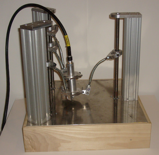 Completed
machine (click to enlarge).
Completed
machine (click to enlarge).
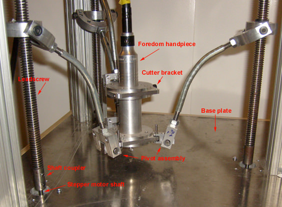 Closeup with details (click
to enlarge).
Closeup with details (click
to enlarge).
1.2 Objective
My goal is to design and build a desktop mill that is much lower cost (>50% cheaper) and much easier-to-use than existing products. To meet these goals, CNC path planning will be done by software running on the host computer, eliminating the need for a microcontroller board, and further reducing cost. To make installation simple, the design will plug into any USB-capable computer (no parallel port required).
To the end user, the desktop mill will look a lot more like a printer than a mill. Software will be automatically installed when the mill is first plugged in (just like any USB device). A minimal g-code interpreter will be built into the printer driver, so that text files can be sent directly to the device for milling, using existing print-capable applications (e.g. Notepad).
To increase accuracy (while keeping costs low), a unique tripod design will be used. Unlike more traditional designs, where the error is a function of the sum of the individual axis errors, the cutting path error in a tripod mill is a function of the average of the individual axis errors. So, for a given parts cost, a tripod design can result in higher overall accuracy. Note, however, that all the control electronics and software developed for this tripod mill can be reused for other, more traditional designs.
1.3 Design details
A tripod mill is similar to a triaglide, but instead of three parallel linear slides above the working area, a tripod mill uses three parallel linear slides surrounding the working area, as shown here. Fixed-length struts connect each linear bearing to the cutter assembly in the center, which is held perpendicular to the table with a parallelogram from one (or more) of the slides. These fixed-length struts, and the cutter handpiece holding assembly will be modeled shown in the next version of the rendering.
 A simplified
2D diagram of the kinematics is shown to the left. The blue lines represent
fixed length struts. To move the cutter up or down in Z,
both leadscrews (shown in red) move up or
down in unison. To move the cutter left (-X), both leadscrews have
to
move -- the
leadscrew
on the left moves up, and the one on the right moves down. In this case,
the end mill will move to the left with no change in Z.
In three dimensions, the
math is
a
little
more complex, but the principles are
the same.
A simplified
2D diagram of the kinematics is shown to the left. The blue lines represent
fixed length struts. To move the cutter up or down in Z,
both leadscrews (shown in red) move up or
down in unison. To move the cutter left (-X), both leadscrews have
to
move -- the
leadscrew
on the left moves up, and the one on the right moves down. In this case,
the end mill will move to the left with no change in Z.
In three dimensions, the
math is
a
little
more complex, but the principles are
the same.
The blue fixed-length struts create parallelograms, which prevent the cutter assembly from tilting or twisting (only one parallelogram is necessary, but more can be used to provide additional stiffness, by overconstraining the cutter assembly).
A Foredom flexible shaft unit provides about 1/6 horsepower of cutting power, while keeping the weight of the cutting assembly as low as possible. Low cutter weight and high cutter speed (>15000 RPM) means that the cutter assembly can be moved very fast, even with very low cost stepper motors.
Since the spindle speed is so high, small cuts per flute can be taken, providing a high quality finish. Since small cuts provide very little back pressure on the cutter assembly, less stiffness is required in the machine as a whole to achieve a given desired accuracy.
To prevent backlash, this design uses nuts that are cast directly onto the leadscrew. The casting material will be West System Epoxy mixed with graphite, to provide a stiff, almost-zero-backlash nut that has very little friction against the leadscrew. This method maintains high accuracy with much cheaper ACME leadscrews, rather than expensive ballscrews and anti-backlash ball nuts.
Leadscrews are 1/2"-10TPI ACME screws from MSC Direct. Error mapping can be done in software, to correct any inaccuracies in each leadscrew.
The stepper controller board uses Allegro SLA7062M chips, which accept step and direction pulses, and provide up to 16X microstepping control for unipolar motors. HobbyCNC provides a 4-axis kit using the Allegro chipset, although they provide the higher currrent (and more expensive) SLA7062 chips. In future versions of the controller (Phase 2), the cheaper SLA7060 chips may be used to further reduce cost.
A single FTDI 2232M chip (available in pre-wired module form from DLP Design) provides 2 high-speed USB ports, which can be configured as 8-bit parallel (to drive up to 4 stepper motors with STEP/DIR), or serial (to drive a serial LCD display). A high-speed "Asynchronous Bit Bang Mode" strobes out 8-bits every 6.5uS, so that all the stepper motors are clocked together. Two bytes are required for each step, since the clock must transition from low to high.
The maximum calculated speed of this design (assuming no loading, 1.8° steppers, 16X microstepping, and a 10TPI leadscew) is then:
1 microstep/(2*6.5us)
= 76923 microsteps/second = 76923/(200*16) = 24 revs/sec = 24 revs/sec / 10TPI = 2.4 inches/sec = 2.4 * 60 = 144 ipm
This is far more speed than the mill will be capable of using.
2 Project Plan
2.1 Project phases
The project will be implemented in three phases:
Phase
|
Mechanical | Electronics | Software | Documentation |
|---|---|---|---|---|
1a
|
Basic 3-axis tripod |
DLP-2232 USB module |
Control console with jog |
Drawings for mechanical
parts Rendering |
1b
|
Cutter
assembly and struts |
tested |
tested |
Schematics for electronics Listings for software |
2
|
Enclosed base |
Custom PC board, using 2232M and Allegro chipsets LCD Display Spindle on/off control |
Minimal g-code interpreter 4th axis interpolation Line/arc blending |
Updates to all docs |
3
|
Touch probe | Jog wheel with detent Spindle variable speed control |
Add cutter compensation |
Updates to all docs |
Here's what I have at the end of this 12-week term:
- Drawings for all of the mechanical parts (e.g. base plate, top plate, cutter bracket, pivot assembly, supports, shaft coupler, leadscrew, fixtures), using Alibre Express
- HobbyCNC board (built and tested)
- DLP-2232 module has been connected with a temporary wiring harness and tested
- Initial line and arc software has been written (trapedoidal velocity on line only, so far)
- Minimal g-code interpretation software (from phase 2)
- I have partially rendered what the partially assembled machine will look like when complete, using Carrara Studio. This rendering is shown at the top of this page, and does not yet include the struts or cutter assembly.
- Mockups of printer dialogs for Windows.
- Printed documents are provided at the end of this packet.
- This quarter, I designed and fabricated the cutter assembly bracket, the pivot brackets, many delrin bushings, the struts, several fixtures, the wood base, and I assembled the entire thing.
- The prototype has been tested, and it basically works. However, the build volume is very small, relative to the size of the machine itself. And, the kinematic calculations were complex. So, future machines will use a more standard design (e.g. orthogonal axes).
%2Band%2BGrease.%0D%0A%2B%2B%2B%2B%2B%2B%2B%0D%0A%2B%2B%2B%2B%2B%2B%2B%0D%0A%2B%2B%2B%2B%2B%2B%2B&image=k_5240_200pix.jpg&weight=0&taxable=True&oversized=False&freight=0&fspecial=&tspecial=&start=1&category=206)